
ReasoningCampus · SHL Inductive and Spatial Reasoning
SHL mechanical comprehension practice starts with the physical relationship and the assumptions in the question. Work through idealised levers, pulleys and gears, checking force, distance and direction separately. The examples are learning models, not claims about a particular employer’s test. ReasoningCampus uses these original worked examples to explain the mechanical principles behind the answers.
Independent learning resource · English · Content revised 16 October 2026
View full preparationSHL mechanical comprehension: draw the physical relationship
At ReasoningCampus, we teach identify the system, mark the forces or motion, state the assumptions, calculate. A memorised shortcut is only reliable within its conditions. For example, the direction rule for two meshing external gears is not automatically a rule for a belt drive or gears fixed to the same shaft.
Levers: compare turning effects
Moment about the pivot = force × perpendicular distance from the pivot
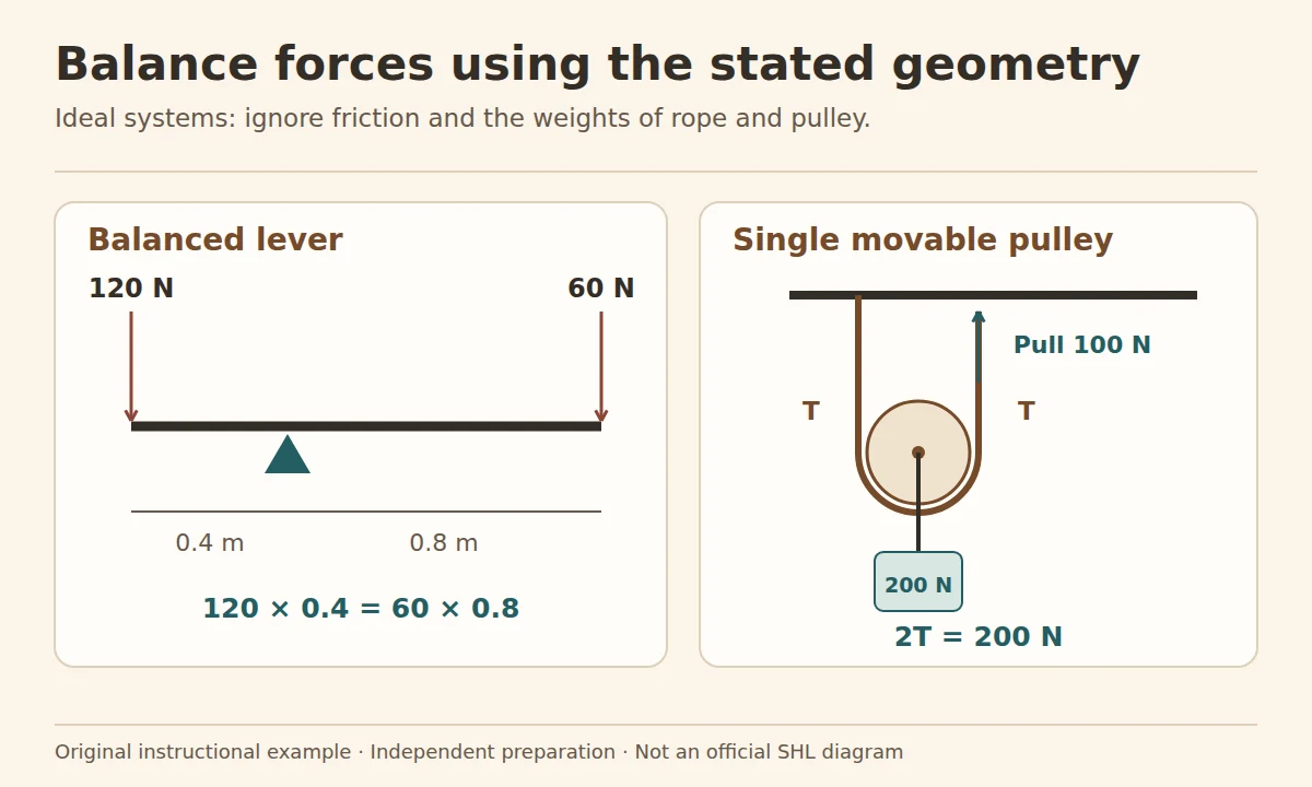
An ideal horizontal lever is balanced. A downward 120 N load acts 0.4 m from the pivot on one side; a downward effort acts 0.8 m away on the other. Balance requires effort × 0.8 = 120 × 0.4. The effort is 48 ÷ 0.8 = 60 N. We ignore the lever’s own weight and friction in this practice example. Doubling the effort arm halves the required effort under those assumptions.
The distance must be perpendicular to the force’s line of action. Do not apply the horizontal example unchanged to a diagram with angled forces.
External gears: direction and tooth count
Two externally meshing gears turn in opposite directions. Along a simple chain of such gears, each mesh reverses direction. With one intermediate gear, there are two reversals, so the first and last turn in the same direction. Count meshes, not a vaguely described number of “gears between”.
Driver speed × driver teeth = driven speed × driven teeth
A 20-tooth driver turning at 60 rpm drives a 40-tooth gear at 60 × 20 ÷ 40 = 30 rpm, in the opposite direction. The larger gear turns more slowly because more teeth must pass the contact point per revolution.
Ideal pulleys: count supporting rope segments
For an ideal single movable pulley supporting a downward load of 200 N, two vertical rope segments each provide 100 N of upward tension. A pull of 100 N at the free end balances the load, ignoring friction and pulley weight. Pulling 2 m of rope through the system raises the movable pulley and load by 1 m. A fixed pulley that only changes the pull direction does not, by itself, provide this force advantage.
| System | Useful relationship | Assumption |
|---|---|---|
| Balanced lever | Equal opposing moments | Known perpendicular arms |
| External gear pair | Inverse speed-tooth ratio | Meshing external gears |
| Movable pulley | Load shared across supporting segments | Ideal rope, equal tension, stated geometry |
Check plausibility before choosing
A longer lever arm should need less force for the same moment. A larger driven gear should rotate more slowly than a smaller driver at the same mesh speed. A pulley advantage in force comes with a distance trade-off. These checks can reveal a reversed ratio, but they do not replace reading the diagram.
A gear train: separate direction from speed
Original idealised example: an external gear A with 20 teeth drives B with 40 teeth, which drives C with 10 teeth. All three are simple meshing gears; there is no compound shaft and no slip. A turns clockwise at 60 revolutions per minute.
B turns anticlockwise at 60 × 20/40 = 30 rpm. C turns clockwise at 30 × 40/10 = 120 rpm. There are two direction reversals, so A and C turn the same way. The intermediate gear changes the two local ratios, but the overall speed ratio is 20/10 = 2.
A common error is to count two meshes and assume the final speed is halved twice. Tooth counts determine speed; mesh count determines the number of direction reversals in this stated model.
Check your understanding: original practice
Sketch the forces or motion and state the idealised assumptions. Check your answer against the physical relationship, not just the shape of the diagram.
Looking for a structured course alongside these free questions? View full preparation.
Questions about SHL mechanical comprehension
Do all adjacent rotating parts turn in opposite directions?
No. The rule here concerns externally meshing gears. Belts, internal gears and shared shafts require their own geometry.
Can I ignore friction?
Only when the task states or clearly uses an idealised model that permits it. The practice examples here explicitly make that assumption.
Does a pulley always halve the force?
No. Count the rope segments that support the moving load and use the specified arrangement. A fixed direction-changing pulley alone does not automatically halve it.
Sources and scope
The retirement notice distinguishes the named 2010 and 2014 Mechanical Comprehension versions. It does not establish the item types in your own invitation. The force and gear calculations here follow the stated idealised assumptions.
Where to go next
Use spatial practice for orientation, the numerical reference for ratios and the invitation guide to check whether mechanical tasks belong in your assessment.
